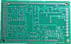
Solder side of PCB
|

Component side of PCB
|
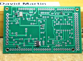
SMD Devices mounted on solder side of PCB. Gray rectangle in upper left is the Precision Clock Oscillator, and the larger device in the bottom middle is the 3.3V regulator.
|
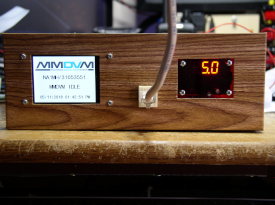
MMDVM/DMR status is displayed on the LCD (left), Voltage regulator displaying 5 Volts (right), and Ethernet/Internet connection (middle).
|
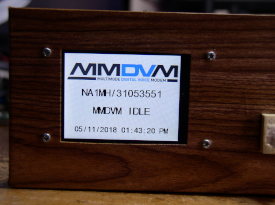
Close up of LCD Display
|
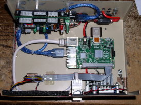
Raspberry Pi mounted on bottom of enclosure
|
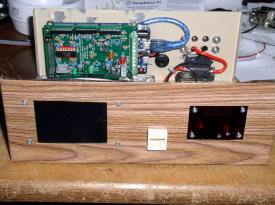
Arduino DUE and MMDVM PCB mounted on back of enclosure
|
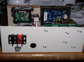
Terminal Block for 12 Volt Supply connection, and below it a 2 A. Fuse
|
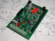
MMDVM Circuit Board, contains two Low Pass Filters, Precision Clock Oscillator, and 3.3 Volt Regulator
|
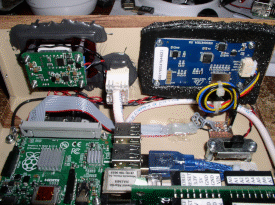
Inside of Front Panel showing the 5V Regulator and the LCD board
|
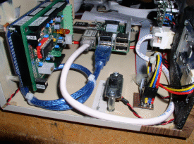
This view shows the added Slide Switch to disconnect the 5V Supply from the other boards, if adjustment to the 5V regulator is needed
|
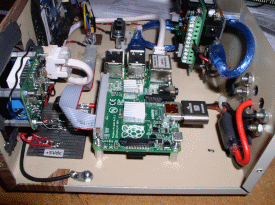
In this view the Terminal Strip on the MMDVM Board is visible, Repeater Radios will be connected to that terminal Strip. On connection at this point is the 5 Volts to operate the MMDVM Board and Arduino DUE.
|